We have a German customer who specializes in automotive injection molds. In their workshop, they have a machining center dedicated to drilling ejector plate holes. The ejector plate is 65mm thick, and they need to drill over 80 holes of 8.1mm diameter.
The task seems simple, but problems kept arising.
Initially, they used a certain brand of drills, which were quite expensive, but the drills would break after just thirty or so holes. When a drill broke inside, they had to use EDM to remove it, wasting half a day per hole. Then they switched to another brand, which had a longer life but poor chip evacuation—when drilling to 40mm depth, chips would clog the flutes, torque would spike, and snap, the drill would break again.
They approached us and asked if we could make a drill specifically for ejector plates.
We looked at their working conditions: the material was SKD61, hardness HRC42, through holes, side cooling, spindle speed 4500 RPM, feed rate 0.08mm/rev. What was the problem? The standard drill's flute design was too conservative, with insufficient chip space, making it impossible to evacuate chips at deeper depths.
We customized an 8.1×61mm drill for them. The 61mm flute length could drill through the 65mm plate in one pass, eliminating the need for pecking. The flute was deepened and widened, and the helix angle was slightly increased to allow chips to flow out smoothly. The core thickness was also graduated—thicker near the point for strength, thinner near the shank to create space for chips.
Most importantly, the point angle was set to 140°. Why not 118°? Because SKD61 is hard, and a 118° point is too sharp—the cutting edge would chip quickly. A 140° point is blunter, with a stronger cutting edge that can withstand impact, and the chips are shorter and less likely to tangle.
They tested the first batch of 20 drills and drilled over 4,000 holes without a single break. They called us and said: "Your drills go in smoothly, come out cleanly, and give us peace of mind."
The mold manufacturing industry may appear rough on the surface, but it is incredibly precise.
A single mold can have anywhere from dozens to hundreds of holes. If a guide pin hole is off, the mold halves won't close properly; if an ejector pin hole is stuck, the product won't eject; if a cooling channel is misaligned, the mold temperature can't be controlled. Any problem with any hole means rework and financial loss.
Our factory has been producing solid carbide drills for over a decade, with customers worldwide, a large proportion of which are mold manufacturers. Over the years, the deepest realization we've had is this: there are no one-size-fits-all solutions in a mold shop, only specific problems and the right drills to solve them.
Today, without piling on jargon, we'll discuss how solid carbide drills are actually used in mold manufacturing, based on the products we've actually made.
In the early years, mold factories mostly used high-speed steel (HSS) drills. Back then, mold steel hardness wasn't very high—H13 and P20 were mainstream, and HSS drills, after sharpening, could handle them.
Now, it's different. Mold life requirements are increasingly demanding, and steel hardness has generally risen to HRC40 and above, with some pre-hardened steels reaching HRC50. HSS drills wear quickly and have low efficiency when machining such materials, often requiring re-sharpening after just a few holes, completely failing to keep up with the pace of automated production.
Solid carbide drills were developed precisely for this challenge.
Carbide is hard, wear-resistant, and possesses excellent hot hardness—it maintains its hardness even at cutting temperatures of 700-800°C. This means higher cutting speeds, more holes drilled, and less frequent tool changes. For a mold shop, this translates directly into increased productivity.
But the drills we make for our customers are never just standard products shipped out. Behind every order is technical communication aimed at solving a specific problem.
We have a series of drills, all featuring spiral flutes, double margins, a 140° point angle, and TiAlN coating. This combination works exceptionally well in mold machining for a simple reason—mold steel is hard, so the drill needs to be hard too.
Many people overlook the point angle parameter, thinking it's just the angle at the tip, and a few degrees don't matter. In reality, a few degrees make a huge difference in a drill's behavior.
The 118° point angle is the standard general-purpose type. It cuts soft materials lightly and efficiently, but when it encounters hard materials, it suffers—the cutting edge is too sharp and prone to chipping. The 140° point angle is significantly blunter than 118°, with a thicker, stronger cutting edge. When drilling hard materials like mold steel, the cutting resistance is high; if the cutting edge is too thin, it will chip quickly. The 140° point angle can withstand this force, keeping the edge stable.
Another advantage is chip control. Drilling soft materials with a 118° point produces long, curled chips that easily tangle around the drill. The 140° point produces relatively thicker, shorter chips that are easier to break and evacuate. In deep hole machining, smooth chip evacuation is paramount—if chips clog the flutes, the drill can't turn, leading to either breakage or scratched hole walls.
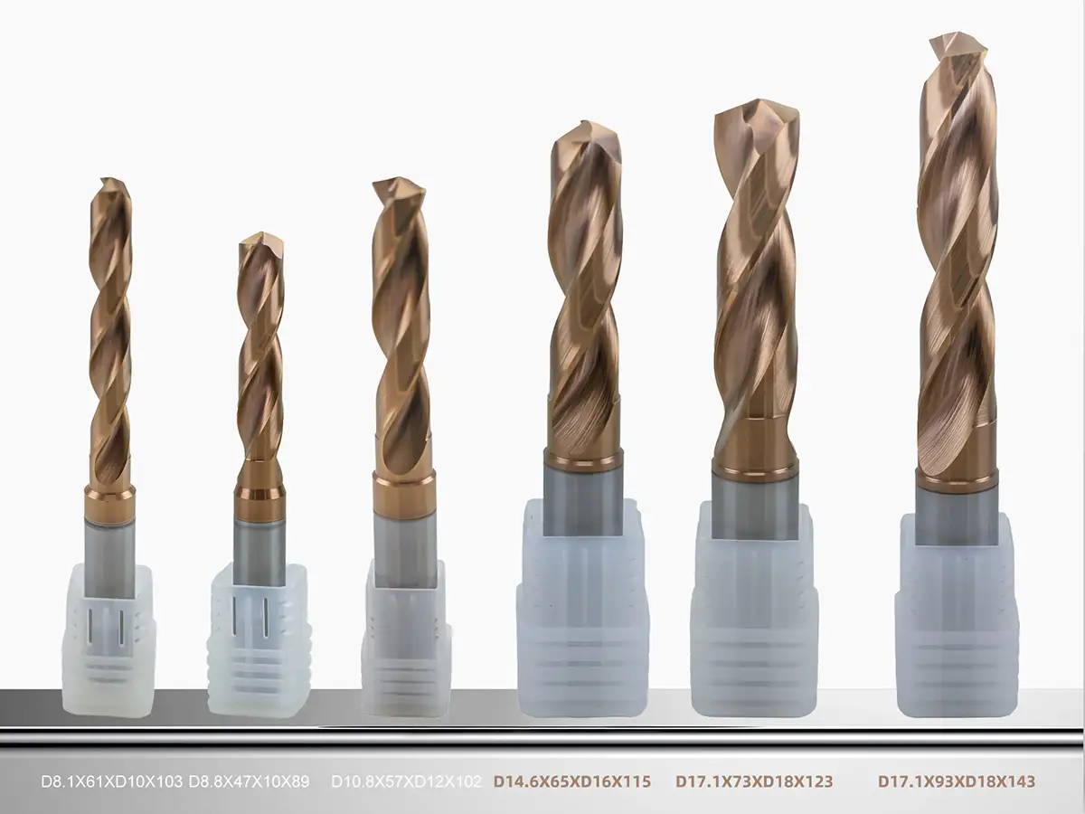
The drills we make for customers range in diameter from 8.1mm to 17.1mm and flute lengths from 47mm to 93mm, all with a unified 140° point angle, precisely because this angle covers the majority of mold steels. Whether it's HRC40 pre-hardened steel or HRC50 hardened steel, it can handle them.
Now, let's talk about double margins. Standard drills have only two margins, while double margin drills have four supporting lands distributed around the circumference. This design is particularly useful in mold machining.
When drilling deep holes, the slender drill tends to wobble as it rotates. Wobbling enlarges the hole and degrades its roundness; in severe cases, it can create a bell-mouthed shape. Double margins act like adding four support points to the drill, making it much more stable during rotation, reducing runout, and ensuring the hole's straightness and roundness.
The advantage of double margins is especially evident when drilling reference holes like guide pin holes. Guide pin holes require good cylindricity and high surface finish; otherwise, the guide pin fit will be poor—either too loose causing play, or too tight causing seizure. Holes drilled with double margin drills have their walls repeatedly smoothed by the four margins, resulting in a significantly better finish than standard drills.
We once made a batch of 17.1mm drills for a mold base manufacturer, specifically for drilling guide pin holes. They previously used a certain brand of drills, and the perpendicularity consistently exceeded the tolerance by 0.02mm. After switching to our double margin drills, the perpendicularity was controlled within 0.01mm. The factory manager simply said, "We'll stick with these from now on."
The role of the spiral flute is to carry chips out of the bottom of the hole. In mould processing, there are many deep and blind holes, and if chips can't escape, it can cause serious issues.
The design of the spiral flute is critical. If the spiral angle is too large, chip removal is fast, but the drill body becomes less rigid and may vibrate. On the other hand, if the spiral angle is too small, rigidity is increased, but chip removal becomes slower, and clogging can occur. When machining hard materials like mould steel, it’s generally best to use a moderately large spiral angle to ensure smooth chip removal without sacrificing rigidity.
Another important factor is the flute’s volume. For the same diameter drill bit, a deeper flute provides a larger chip space, making chip removal easier, but it results in a thinner drill core and reduced rigidity. Conversely, a shallower flute gives a thicker drill core, improving rigidity but offering less space for chip evacuation, which can lead to clogging. This balance is crucial and requires experience. For hard materials and small chips, less chip space is acceptable. But for softer materials and longer chips, a larger chip space is essential.
We made a batch of 8.1mm drill bits for a mould factory in Guangdong specifically for drilling ejector pin plate holes. The ejector pin plate was 65mm thick, and required over 80 holes of 8.1mm diameter, with the material being SKD61 at a hardness of HRC42. The original drill bits used by the factory clogged with chips when drilling beyond 40mm and would break after a few attempts. We customized the flute by deepening and widening it and increasing the spiral angle slightly to allow the chips to evacuate more easily. The customer tested the first batch of 20 drill bits, drilling over 4,000 holes without a single break.
Carbide itself is hard enough, but when directly used to drill mould steels, it still struggles with the high cutting temperatures. Mould steels contain alloying elements like chromium, molybdenum, and vanadium, which act like sandpaper on the drill bit during cutting, and coupled with high temperatures, the drill bit wears down quickly.
The purpose of the TiAlN coating is to apply a protective layer to the surface of the drill bit. When the temperature increases, this layer forms an aluminium oxide layer. Aluminium oxide has poor thermal conductivity, acting as a heat shield for the drill bit, preventing heat from entering and allowing the heat to be carried away by the chips. The base of the drill bit stays at a relatively low temperature, preserving its hardness and extending its life.
Coated drill bits can achieve cutting speeds over 30% higher than uncoated bits. For larger bits, such as the 17.1mm ones, a linear speed of 80-100 meters per minute is completely feasible, and the efficiency improvement is significant. Additionally, the coating provides lubrication, making chip removal smoother and preventing chips from sticking.
We have a German customer who specializes in high-hardness moulds, with materials heat-treated to HRC52. They tried several suppliers’ drill bits, but the lifespan was only around 20 holes per bit. After we applied the TiAlN coating and adjusted the point angle to 145°, the lifespan increased to 80 holes. The customer now orders 100 drill bits per month.
Some customers have asked us why some of our drill bits are not in whole-number sizes, like 17.1mm, 14.6mm, and 8.1mm.
The answer is in the mould drawings.
Many holes in mould designs are nominally 17mm, but the actual fit tolerances require some clearance. If the drill bit is exactly 17mm, the reamed hole might end up at 17.02mm, resulting in a loose fit. If the drill bit is made 17.1mm, the reamed hole will be between 17.02-17.03mm, providing a perfect fit.
While the 0.1mm difference seems small, in mould fitting, even a tiny discrepancy can make a big difference.
The same logic applies to the 8.1mm size. Many ejector pins have a standard diameter of 8mm, but a small gap is needed between the ejector pin and the plate to allow smooth movement. 8.1mm is the ideal size for this gap.
These non-integer sizes are the best values based on long-term customer experience. We’re not just making drill bits; we’re creating tools that solidify these experiences.
Our range of drill bits, with diameters from 8.1mm to 17.1mm and cutting lengths from 47mm to 93mm, is designed to meet specific processing scenarios.
8.1×61: A long, slender drill bit specifically designed for deep holes in ejector pin plates. With a typical thickness of 50-70mm for the pin plate, the 61mm cutting length allows the bit to drill through in a single pass without needing a tool change. The deeper and wider flute ensures smooth chip removal in deep holes.
8.8×47: This size matches the standard 3xD drill bit and is a versatile choice for drilling medium-depth holes. The 47mm cutting length provides good rigidity and high efficiency.
10.8×57 and 14.6×65: These medium-sized drills are used for drilling cooling channels or insert positioning holes. Their cutting lengths of 57mm and 65mm strike a balance between rigidity and chip removal, ensuring they can drill to the required depths without compromising performance.
17.1×93 and 17.1×73: These drill bits are ideal for drilling guide pillar holes. For large moulds, the template thickness is usually between 80-100mm, and the 93mm cutting length is perfect for drilling through in a single pass. For thinner templates, the 73mm version offers better rigidity.
Each size is designed for a specific scenario in mould processing, and the value of customization lies in adapting the drill bit to the customer’s requirements, rather than forcing the customer to fit standard products.
Mould Hole Types According to Function and Their Key Technical Requirements
| Hole Type | Typical Application | Key Technical Requirements | Common Diameter Range | Length-to-Diameter Ratio Range |
|---|---|---|---|---|
| Reference Hole | Guide pillar hole, guide sleeve hole | Verticality ≤0.01/100mm, Positioning tolerance ≤±0.02mm | 12-25mm | 3-8x |
| Functional Hole | Ejector pin plate hole, return pin hole | Hole diameter tolerance H7-H8, Surface roughness Ra ≤1.6μm | 3-12mm | 5-15x |
| Process Hole | Cooling channels, heating rod holes | Positioning tolerance ≤±0.1mm, No step in hole wall | 6-20mm | 5-20x |
The specificity of mould processing means that standard drill bits often struggle to perfectly match the actual working conditions. The core of customized size design lies in translating process requirements into precise tool parameters.
The design of the cutting length needs to consider three key factors: hole depth, chip removal space, and tool rigidity.
One-Pass Drilling Principle: For through-hole drilling, the cutting length should be 2-5mm longer than the hole depth to avoid issues caused by tool changes, such as tool marks and secondary positioning errors. For example, in the 93mm cutting length version, the goal is to drill through a template thickness of 80-90mm in one pass.
Rigidity Priority Principle: For blind hole drilling, the cutting length should not be overly excessive. An excessively long cutting length not only increases tool costs but also reduces rigidity. The 73mm cutting length version is optimized for hole depths of 50-70mm, balancing the need to meet the processing requirements while maximizing rigidity.
The design of the shank diameter must match the clamping range of the machine tool's tool holder while also considering clamping rigidity and interference avoidance.
Reinforced Shank Design: For a cutting diameter of 17.1mm, paired with an 18mm shank diameter, this is a typical reinforced shank design. Compared to a 17mm straight shank, the 18mm shank offers greater clamping force and rigidity. Compared to a 20mm standard shank, this design avoids the hassle of changing to a larger tool holder.
Neck Reduction and Interference Avoidance Design: For a cutting diameter of 8.1mm paired with a 10mm shank diameter, this design features a neck reduction structure. The finer cutting part allows for deeper access into narrow spaces, while the thicker shank provides stable clamping, commonly used for insert processing and similar operations.
Mould drawings often feature non-integer diameters (e.g., 17.1mm, 14.6mm, 8.1mm), which are not design flaws, but rather the result of precise calculations based on fit tolerances.
For example, with a guide pillar hole, the nominal diameter may be 17mm, but the finished product typically requires a size of 17.02-17.03mm. If a 17mm drill bit is used, the reamed hole allowance would be only 0.02-0.03mm, making it difficult to ensure quality reaming. By using a 17.1mm drill bit, the reamed hole allowance can be controlled at 0.07-0.08mm, ensuring both the stability of the reaming process and providing adjustment space for the final dimensions.
The same logic applies to 8.1mm diameter drill bits commonly used for ejector pin plate holes. The nominal diameter of the ejector pin is 8mm, and a slight gap of 0.05-0.1mm is required between the pin and the plate to ensure smooth pin movement. Thus, 8.1mm is the optimal choice.
These non-integer sizes are the best values derived from years of customer experience. We are not just manufacturing drill bits; we are creating tools that encapsulate this accumulated knowledge.
The management of carbide drill bit life should follow the principle of economic tool life, rather than maximum tool life.
Conduct cutting tests and record the number of holes drilled from the new tool until it fails.
Plot a wear curve to identify the critical point where the tool’s dimensional stability starts to decline.
Use 70%-80% of the critical point hole count as the threshold for economic tool life.
Fixed Replacement: Replace the tool after a set number of holes, suitable for batch production.
Monitored Replacement: Assess the tool’s condition based on signals such as spindle power and cutting sounds, ideal for automated production lines.
The application of solid carbide drill bits in mould manufacturing has long surpassed the crude "just make a hole" approach. From the mechanical considerations of point angles to the guiding mechanisms of cutting edge structures, to the heat-resistance principles of coating technologies, each technical detail serves a core goal: improving the economic efficiency of mould manufacturing while ensuring processing accuracy.
Mould material properties continue to improve, from HRC40 to HRC50 and even HRC60; the precision requirements are constantly increasing, from 0.02mm to 0.01mm, and even to micron-level precision. These trends place higher demands on drill bit technology. However, the underlying technical principles remain unchanged: precisely matching the tool's geometric parameters with the specific processing needs.
Whether it is controlling the verticality of guide pillar holes, removing chips from deep holes in ejector pin plates, or drilling angled entries into cooling channels, each processing challenge is solved based on a profound understanding of the working conditions. This is the technical foundation that allows solid carbide drill bits to continuously meet the ever-evolving demands of mould manufacturing.
 We like to do design according to all the customers' requirements, or offer them our new designs. With strong OEM/ODM capabilities, we can fill your sourcing demands.