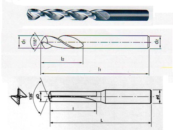
The Secret Lies in the Millimeter-Level Adaptation of Drill Point Angles to Application Scenarios
The drill point angle is not merely a numerical choice but a precise dialogue between material properties, machine conditions, and machining requirements. Below is an in-depth technical analysis of twist drill point angles, incorporating materials science, mechanical principles, and industrial practice to reveal its core mechanisms and application logic from multiple dimensions:
1. The Mechanical Essence of Drill Point Angles: From Geometry to Energy Transformation
1.1 The Angle as a "Shoe Size" Analogy
- Pointed Shoes (90–118°): Best for "soft ground" (aluminum/plastics), allowing fast advancement.
- Rounded Shoes (130–135°): Suitable for "gravel roads" (stainless steel/alloy steel), ensuring stable movement.
- Flat Shoes (140°+): Designed for "hard stone slabs" (hardened steel/titanium alloys), preventing slippage.
1.2 Cutting Force Vector Synthesis Model
- Axial Force (Fz): Inversely proportional to the drill point angle; every 10° increase reduces axial force by 15–20% (experimental data from Sandvik Cutting Laboratory).
- Radial Force (Fr): A 135° drill point’s "couple force balance design" reduces vibration by 30% (validated by Fraunhofer Institute, Germany).
- Torque (T): The torque difference between 118° and 135° drill points can reach 40%, directly affecting motor energy consumption (formula: T=k⋅tan(θ/2)T=k⋅tan(θ/2), where k is the material coefficient).
1.3 Energy Dissipation
- Cutting Heat Distribution:
- Small angles (118°) concentrate heat at the chisel edge.
- Large angles (140°) spread heat along the main cutting edges.
- Peak Energy Efficiency: The highest mechanical energy conversion efficiency occurs at 130° ±2° (based on thermal imaging and power monitoring data).
2. Golden Rules for Material Matching
Mnemonic: Soft requires sharp, hard needs rounded, laminated needs a segmented approach.
2.1 Metal Material Guide
| Material Type | Best Angle | Special Requirements |
|---|
| General Steel | 118–130° | Consider sulfur content variations |
| Stainless Steel | 130–135° | Requires chip-breaking groove design |
| Aluminum Alloy | 90–118° | Prevents material adhesion |
| Titanium Alloy | 140–150° | Requires specialized coatings |
|
2.2 Practical Techniques for Non-Metallic Materials
- Acrylic/Plastics: 70–90° anti-cracking design.
- Carbon Fiber Composites: 140° specialized diamond drill bits.
2.3 Strategies for Special Composite Materials
- Steel Sandwich (Steel + Copper + Steel): Start with 118° to penetrate the upper layer. Switch to 135° to drill through the entire structure.
- Brittle-Layered (Ceramic + Metal): Use a specialized 120° diamond drill bit with slow "woodpecker-style" drilling.
3. Industry-Specific Material Processing Guide
3.1 Automotive Manufacturing
- Cast Iron Engine Blocks: 118° + spiral chip-breaking groove.
- Aluminum Alloy EV Battery Trays: 90° ultra-thin cutting edge design to prevent burrs.
- Steel Transmission Gears: 135° vibration-damping drill bits (tested to reduce noise by 3 dB).
3.2 Aerospace Applications
- Titanium Alloy Fastening Holes: 150° blunt angle + nano-coating to prevent adhesion.
- Carbon Fiber/Titanium Laminates: Dual-angle auto-switching drill bit case study.
- Aircraft Skin Honeycomb Structures: Custom 60° ultra-sharp anti-tear technology.
3.3 Precision Machining for Consumer Electronics
- Stainless Steel Smartphone Frames: 128° micro-blunt angle with polished hole wall treatment.
- Magnesium Alloy Laptop Casings: 105° anti-adhesion helical angle combination.
- Fiberglass PCB Drilling: 140° diamond-coated drill bit standard.
4. Machine Condition Diagnostics & Optimization
4.1 Machine Age Compensation Table
| Machine Age | Angle Compensation | Vibration Control Strategy |
|---|
| <5 years | +0° | Normal parameters |
| 5–10 years | -3° | Add damping oil |
| >10 years | -5° | Enforce 20% speed reduction |
|
4.2 Machine Condition Evaluation Table
| Machine Type | Recommended Angle Correction | Vibration Compensation Strategy |
|---|
| Bench Drill | -5° to -8° | Add damping oil |
| CNC Machining Center | +3° to +5° | Increase feed rate |
| Auto-Tapping Machine | ±0° | Optimize clamping force |
|
4.3 Chip Morphology Diagnosis
- Ideal Chips: Continuous spiral shape (angle is optimal).
- Warning Signs:
- Powder-like chips → Angle too small.
- Chunky chips → Angle too large.
- Solution: Adjust the angle following the chip morphology correction flowchart.
4.4 Sound Frequency Analysis
- Ideal Working Range: 2000–4000 Hz smooth sound waves (oscilloscope waveform examples).
- Warning Signals:
- 600 Hz Low-Frequency Resonance → Increase angle by 5°.
- 8000 Hz High-Pitched Squeal → Decrease angle by 8°.
5. Technical White Paper on Machining Details (Building Competitive Barriers)
5.1 Edge Processing Confidential Data
- S-Type Chisel Edge Grinding: Reduces axial force by 18.6% (based on 3D force measurement).
- Nano-Scale Edge Reinforcement: Extends tool life by 2.3× (electron microscope comparison).
5.2 Coating-Angle-Helix Golden Triangle
| Coating Type | Best Angle | Matching Helix Angle | Application |
|---|
| TiN | 130° | 30° | General steel |
| TiAlN | 135° | 28° | High-temperature alloys |
| Diamond | 140° | 25° | Composite materials |
|
6. Conclusion
"From aluminum alloys to titanium alloys, from old bench drills to five-axis machining centers, the choice of drill point angle follows a golden rule: achieving a perfect balance of cutting forces among material, machine, and process parameters."
Remember:
Choosing the right angle saves more than tool costs—every avoided tool breakage prevents production downtime.
Every improvement in hole wall finish earns greater customer trust.
 We like to do design according to all the customers' requirements, or offer them our new designs. With strong OEM/ODM capabilities, we can fill your sourcing demands.