Practical Techniques for Standardizing Non-Standard Tap Order Drawings
In the global hardware tooling trade, the standardization of drawings for non-standard tap orders has long been a core pain point for manufacturers. With customers spanning different countries, industries, and standards systems, drawings often include mixed notations, missing key parameters, or vague process requirements. These issues frequently lead to rework, delivery delays, or even batch scrapping. According to industry surveys, approximately 65% of international tooling disputes stem from misinterpretation of drawings.
Based on frontline manufacturing experience and technical validation, this article outlines a complete workflow solution—from drawing interpretation and parameter conversion to risk control. Focusing on actionable techniques and real-world data, it provides a replicable methodology for addressing the challenges of converting non-standard orders into production-ready specifications.
Tip 1: Three Key Points to Spot “Traps” in Drawings Quickly
1. Check for Mixed Thread Standards
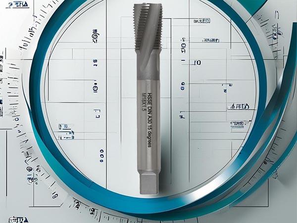
- European clients often embed DIN notations subtly (e.g., a chamfer angle of 55° instead of the ISO standard 60°).
- Japanese and Korean drawings frequently use JIS-specific symbols (e.g., "▽" for surface roughness).
- Suggestion: Post a comparative standards chart on the design department wall.
| Client Notation | National Equivalent | Common Pitfall |
|---|
| R0.1 MAX | Ra 0.8μm | Don’t convert by number directly |
| DIN376-2 | GB/T 20325 | Watch for differences in spiral angle |
2. Check Whether the Dimensional Chain Closes For hand-drawn sketches:
- Circle all reference baselines in red.
- Back-calculate key dimensions (e.g., total length = cutting section + calibration + shank).
- Case: An Indian customer omitted the shank diameter; catching this early avoided mass scrap.
3. Watch for Material Processing Requirements
If a drawing notes “high hardness,” confirm the exact HRC.
“Special coating” must be specified—TiN, TiCN, or AlCrN?
Tip 2: Four-Step Guide for Interpreting Ambiguous Drawings
(Shop-floor approved!)
- Step 1: Draw a “Three-Line Diagram” Use color coding:
- Red = confirmed dimensions from client
- Blue = industry-standard values (e.g., cutting length = 1.5 × pitch)
Green = items needing clarification
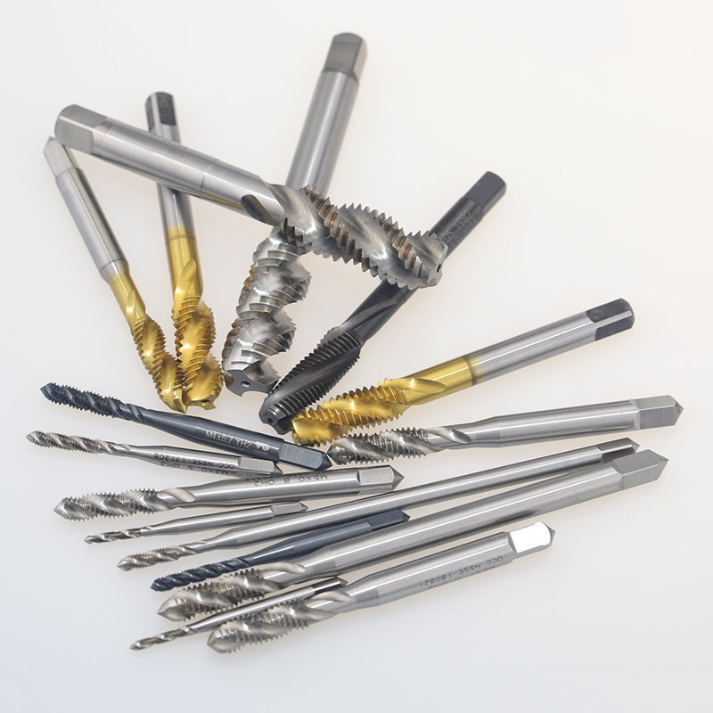
- Step 2: Use Physical Samples Build a photo catalog of typical tap structures.
- When the customer can’t describe the flute type, ask: “Like Type A or Type B?”
- Step 3: Try a Trial Tool For fully unclear specs:
- Use in-stock tools of similar size for test cuts.
- Record chip evacuation and cutting performance. Case: Used an M8 tap to verify an M7.5 custom order, saving 3 days of clarification time.
- Step 4: Create a Confirmation Checklist Include 10 must-ask items:
- Is this a blind hole?
- What’s the hardness range of the workpiece?
- Machine type (manual or CNC)?
- …(plus other essentials)
Tip 3: Build an Internal Drawing Template Library
1. Categorize by Region and Material
- EU / North America / Southeast Asia templates
- Stainless steel / Cast iron / Titanium alloy versions
2. Add Special Notes Area A yellow-highlighted margin for:
- Client-specific historical requirements
- Recommended cutting parameters for listed materials
3. Anti-Mistake Checklist Include at the bottom of the drawing:
- ☑ Chamfer transition angle noted?
- ☑ Fit tolerance grade specified?
- ☑ Coating thickness clearly stated?
Tip 4: Three Tricks for Handling Rush Orders
- Trick 1: Prioritize Key Dimensions For 24-hour urgent jobs:
- Confirm major diameters first (for raw material prep)
- Verify thread type early (for tap blank selection)
- Trick 2: Partial Drawings First
- Release basic body drawing to start material prep
- Fill in details (e.g., chip groove shape) within 3 days
- Trick 3: Leave Adjustment Allowance
- Reserve 0.2 mm for diameter corrections
- Add 0.05 mm extra groove depth for tweaking
Core Techniques for Parameter Conversion
1. Automatic Thread Parameter Calculator
- Major Diameter Compensation Formula:
- D_actual = D_nominal + (0.05 × HRC / 10)
(For hardened steel HRC > 40)
- Spiral Angle Adjustment Model:
| Material | Base Spiral Angle | Correction Factor |
|---|
| Aluminum | 30° | ×1.2 |
| Stainless Steel | 20° | ×0.8 |
| Titanium | 15° | ×0.7 |
2. Chip Groove Optimization Tool
- Minimum Chip Groove Volume:
V_min = π × (R² − r²) × P × 0.7
(R = outer groove radius, r = base groove radius, P = thread pitch)
- Chip Evacuation Test:
- if machining_length / hole_diameter > 5: use double-flute
- if cutting speed > 15 m/min: add 2° rear clearance angle
Solutions for Industry-Specific Demands
1. Automotive (High Precision Needs)
- VW’s VDA standards:
- 3D profilometer required for full tooth profiling
- Process capability report with CPK ≥ 1.33 mandatory
- Solution: Implement TS 16949 checkpoints
2. Aerospace (Extreme Conditions)
- Boeing’s BAC standards:
- Titanium cutting requires cold air cutting system
- Mandatory X-ray flaw detection report
- Response: Invest in specialized low-temp coating systems
3. Medical Devices (Miniaturization)
- Micro taps (< M1):
- Mirror electro-polishing required
- Full-size inspection with an electron microscope
- Tool Recommendation: Keyence IM-8000 Measurement System
Conclusion:
Standardizing non-standard tap drawings is essentially a precise translation between technical language and manufacturing execution. By establishing mapping rules, refining parameter compensation models, and integrating digital verification tools, manufacturers can convert complex custom requirements into manageable production instructions. From automotive to aerospace, industry-specific demands are driving a new era of agile production response. Looking forward, the convergence of smart recognition technologies and process databases will dramatically boost drawing interpretation efficiency.
We recommend using this methodology as a foundation to systematically accumulate industry know-how and strike a dynamic balance between standardization and flexibility—ultimately realizing the transformation to “non-standard orders, standard delivery.”
 We like to do design according to all the customers' requirements, or offer them our new designs. With strong OEM/ODM capabilities, we can fill your sourcing demands.