strong>In-Depth Guide to Filling Out Non-Standard Cutting Tool Design Request Forms
In the realm of custom cutting tool manufacturing, a well-completed request form is the crucial link between design and production. Vague parameters and missing application details frequently lead to delays, quality disputes, or even batch scrapping. This is especially problematic in export trade, where hidden requirements—such as standard mismatches or material restrictions—may trigger cross-border conflicts. Based on over 20 years of experience in the metalworking tool industry, this guide provides a systematic approach to completing the entire form—from basic specifications to detailed working condition matching. It includes practical details such as material conversion, failure prediction, and cost coordination, helping professionals avoid common pitfalls and efficiently convert technical needs into production-ready solutions.
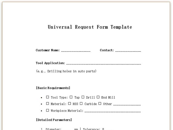
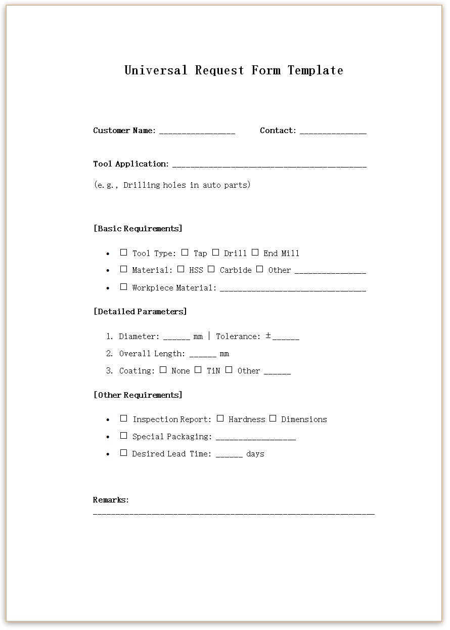
Example: The client requests an "M6 tap" without specifying metric or UNC thread, leading to return or rejection.
A complete form minimizes repeated confirmations between the technical team and the customer.
Clear documentation helps avoid future quality disputes.
| Parameter Type | Correct Example | Incorrect Example |
|---|---|---|
| Dimension | "Diameter 6mm ±0.01" | "About 6mm" |
| Material | "M35 High-Speed Steel" | "Some good steel" |
| Coating | "TiN coating, 2μm" | "Anti-rust coating" |
E.g., “For CNC machining of 304 stainless steel screw holes in batch production.”
Avoid mismatches between Rockwell and Brinell values:
HRC ≈ HB/10 + 3 (Valid for HRC 20–60 range)
| Material | Drill Speed (Carbide) | Feed per Tooth (HSS-E End Mill) |
|---|---|---|
| Aluminum Alloy | 200–300 m/min | 0.1–0.2 mm/tooth |
| Stainless Steel | 30–50 m/min | 0.05–0.1 mm/tooth |
| Titanium Alloy | 15–30 m/min | 0.03–0.06 mm/tooth |
| Failure Mode | Recommended Design Adjustment |
|---|---|
| Chipping | Increase rake angle, reduce hardness by 2 HRC |
| Built-up Edge | Add chip groove, polish cutting edge |
| Chatter | Shorten overhang, apply unequal flute spacing |
A well-structured non-standard cutting tool request form is both a technical document and a quality contract. Through precise parameter definition, working condition mapping, and failure risk assessment, companies can greatly improve the reliability and efficiency of custom tooling solutions. This guide, with acceptance standards, quick-reference charts, and smart templates, transforms abstract technical needs into quantifiable and verifiable benchmarks. Whether you're a new engineer or a seasoned buyer, standardized request forms reduce communication friction and serve as a reusable methodology for tackling complex requirements—paving the way for more efficient collaboration in the customized manufacturing sector.
 We like to do design according to all the customers' requirements, or offer them our new designs. With strong OEM/ODM capabilities, we can fill your sourcing demands.