Comprehensive Technical Analysis of Industrial-Grade Center Drills
In the field of precision manufacturing, center drills, though small, play a pivotal role in determining the machining accuracy of shaft components. As a factory with 15 years of experience in the foreign trade of hardware cutting tools, we have witnessed firsthand how the precise matching of different center drills (Type A/B/R/C/Chamfer) and center holes (Standard/Threaded/Deep Holes) has transformed production efficiency—from micron-level positioning holes in German automotive crankshafts to deep stainless-steel hole processing in Japanese medical devices.
This article demystifies technical jargon and provides practical insights into the combinations of five center drill types and six center hole types. By understanding these combinations, global buyers can avoid pitfalls, reduce costs, and improve efficiency in procurement.
1 In-Depth Analysis of the Five Main Center Drill Types and Practical Selection Strategies
1.1 Type A Center Drill: The Hidden Strength of 60° Taper Tip
(Key Terms: DIN 332 Standard / Stainless Steel Machining / Automotive Parts)
- Structural Analysis
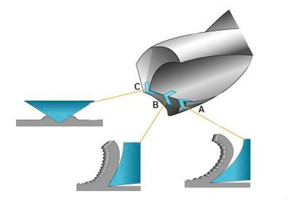
- Dual Protection Design: 60° primary taper for precise positioning + 30° protective taper to prevent scratching (illustrated).
- Special Feature: R0.5 micro-radius treatment, a critical inspection point for European clients.
- Practical Application Tips
- Solving Stainless Steel Machining Challenges: When used on 304 stainless steel, drilling a preliminary Ø1.5-2mm guide hole prevents chipping.
- Automotive Industry Case Study: German Crankshaft Manufacturer Procurement Data (Annual Usage: 20,000 units)
-
- Tool Holder Compatibility: HSK-A63 hydraulic tool holder
- Machining Parameters: 1500 rpm / 0.1 mm/rev feed rate
1.2 Type B Center Drill: The Specialist for Flat-Bottom Countersinking
(Key Terms: ISO 866 Standard / Titanium Alloy Machining / Oil Valves)
- Three-Step Geometry Design
- 118° Tip – Ensures rapid penetration.
- 90° Flat Bottom – Creates a precise, even surface.
- 45° Chamfer – Enhances hole finish.
- Industry Application Comparison
| Application | Recommended Material | Coating Choice | Tool Life (Holes) |
|---|
| Oil Valves | Carbide | TiAlN Coating | 3000+ |
| Agricultural Machinery | HSS-E | Standard Coating | 1500 |
| Medical Instruments | Stainless Steel-Specific | Electro-polished | 2000 |
|
- Solving Customer Pain Points
- Dubai Client Case: When machining 17-4PH stainless steel valve bodies, increasing the helix angle from 30° to 38° improved chip evacuation by 60%.
- Common Mistake: A land width >0.1mm can lead to diameter deviation in flat-bottom holes.
1.3 Type R Center Drill: The Secret Weapon of Precision Manufacturing
(Key Terms: AS9100 Certification / Medical Devices / Arc Cutting Edge)
1.4 Type C Multi-Function Center Drill: The Intelligent Choice for Cost Savings
(Key Terms: DIN 1880 Standard / Labor Optimization / Automotive Wheel Hubs)
- Cost Reduction Formula
- Traditional Process Cost = (Drilling Time + Tool Change Time) × Unit Cost
- Multi-Function Drill Solution = Overall cost reduced by 40%
- Real Case Study: A French automotive wheel hub production line saved €50,000 annually in labor costs.
- Selection Considerations
| Material | Recommended Type |
|---|
| Aluminum Alloy | With Chip Breaker Design |
| Cast Iron | Reinforced Cutting Edge |
| Plastic Special | Rake Angle Treatment |
|
- Inspection Priorities
- Verify the smooth integration of the chamfered surfaces.
- For food-grade processing, an FDA-certified lubricant test report is required.
1.5 Chamfer Center Drill: The Ultimate Solution for Special Conditions
(Key Terms: Optimized Length-to-Diameter Ratio / Nuclear Equipment / Dry Cutting)
- Evolution of Anti-Vibration Design
- First Generation: Constant Helix Angle → Suitable for L/D < 5
- Second Generation: Variable Helix Angle → Suitable for L/D = 5-8
- Third Generation: Waveform Cutting Edge → Suitable for L/D > 8 (Used in Russian nuclear equipment)
- Coating Technology Comparison
| Coating Type | Suitable Material | Heat Resistance | Tool Life |
|---|
| TiN Coating | General Steel | 600°C | Baseline |
| DLC Coating | Aluminum Alloy | 400°C | 1.5× Longer |
| Nano-Composite | High-Temp Alloys | 800°C | 3× Longer |
|
- Special Order Processing
- Radiation-Resistant Orders: Additional tungsten alloy balance weight inspection.
- Dry Cutting Orders: Must undergo surface blackening treatment.
2. Technical Specifications and Drilling Strategies for Center Holes
(Core Keywords: ISO 2540 Standard / Threaded Center Holes / Deep Hole Machining)
2.1 Standard Center Holes
- International Standards:
- ISO 2540 Type R: 60° primary cone angle + 120° protective cone (most common)
- DIN 332 Type A: Allows ±0.5° angle tolerance (critical inspection requirement for German customers)
- Machining Characteristics:
- Applicable Materials: Carbon steel / Aluminum alloy / Cast iron
- Typical Parameters:
► Pre-drilled hole diameter: d = Center hole diameter D × 0.3
► Feed rate: f = 0.05–0.12 mm/rev (adjusted based on material hardness)
- Export Case Studies:
- Exports to Germany: Must provide a DIN 332 compliance inspection report
- Special Requirement from a Korean Customer: A 0.2 mm flat bottom must be retained at the base of the center hole
2.2 Center Holes with Protective Taper
- Structural Innovation:
Dual-Safety Design: 60° working cone + 120° protective cone (as illustrated)
Core Function: Prevents lathe centers from wearing the hole edges
- Industry Applications:
Precision Shaft Machining: Swiss watch components (surface roughness requirement: Ra ≤ 0.4)
Ultra-Long Shaft Machining: China’s high-speed rail axles (anti-vibration solution for shafts over 6m in length)
- Technical Parameters:
| Shaft Diameter (mm) | Protective Taper Depth (mm) | Recommended Drill Type |
|---|
| 10–30 | 1.2–2.5 | Type R |
| 30–80 | 3.0–4.5 | Type B |
| 80–150 | 5.0–6.0 | Customized Type |
|
2.3 Threaded Center Holes
- Revolutionary Design: Tapered Hole + Threaded Composite Structure
- International Standard: ISO 2541 (Thread size range: M6–M24)
- Special Process: Drill center hole → Tap threads → Secondary precision finishing of the taper
- Three Key Advantages:
- Achieves both axial positioning and radial locking of the workpiece.
- Prevents surface scratches caused by traditional offset chucks.
- Particularly suitable for machining thin-walled components.
- Typical Orders:
- Italian High-End Machine Tool Manufacturer: M12 × 1.75 fine-threaded hole.
- Japanese Robotic Joint Components: Requires thread-to-taper coaxiality of ≤0.01mm.
2.4 Deep Center Holes
- Definition: Extra-deep machining where hole depth exceeds five times its diameter.
- Technical Challenges & Solutions:
Chip Evacuation Issues → Solution: Internal-coolant center drills (as illustrated).
Hole Deflection → Control Measure: Retract the drill every 15mm to clear chips.
- Standard Parameters:
| Hole Diameter D (mm) | Max Depth-to-Diameter Ratio | Recommended Drill Point Angle |
|---|
| 2–5 | 8:1 | 90° |
| 5–10 | 6:1 | 118° |
| 10–20 | 4:1 | 140° |
|
- Successful Case Study:
Custom Deep-Hole Drill for Norwegian Marine Crankshafts: L/D = 12:1
▶ Special Design: 40° helix angle + nano coating
▶ Machining Performance: Straightness < 0.03mm/m
3. Function Dictated by Shape:
The Relationship Between Center Drill Geometry and Center Hole Structure
| Center Drill Type | Key Geometric Features | Corresponding Center Hole Type |
|---|
| Type A | 60° primary taper + 30° protective taper | Standard Center Hole (ISO 2540) |
| Design Principle: | The dual-taper structure ensures precise positioning, while the protective taper prevents edge chipping, making it suitable for reference holes in conventional shaft components. |
| Type B | Flat-bottom stepped design + multi-stage taper | Center Hole with Protective Taper |
| Design Principle: | The flat-bottom section forms a protective taper, preventing wear on the lathe center and making it ideal for precision parts requiring axial locking. |
| Type R | Fully rounded cutting edge (R0.8–R3.2) | Deep Center Hole / Precision Center Hole |
| Design Principle: | The rounded edge minimizes stress concentration, extends tool life, and is especially suited for deep-hole machining (L/D > 5) and high-surface-finish applications. |
| Type C | Drill tip + chamfering composite cutting edge | Multi-Function Center Hole |
| Design Principle: | Enables simultaneous drilling and chamfering, reducing tool change time and optimizing efficiency for mass production. |
| Chamfer Type | Multi-angle chamfering edges (30°/45°/60°) | Special Chamfered Center Hole |
| Design Principle: | Custom angles accommodate different assembly requirements, such as anti-vibration chamfering in nuclear equipment. |
| Threaded Center Drill | Tapered tip + thread-forming groove | Threaded Center Hole (ISO 2541) |
| Design Principle: | Simultaneous machining of the taper and internal thread enables axial fixation, replacing traditional clamping methods and preventing surface damage. |
|
4. Key Application Scenarios Analysis
4.1 Protective Taper Design vs. Center Hole with Protective Taper
- Technical Logic: The secondary protective taper (30° or 45°) formed by Type A/B center drills during machining serves as an additional reinforcement.
- Function: Distributes pressure on the lathe center, preventing deformation at the hole entrance—especially crucial for thin-walled parts.
- Supporting Data: For carbon steel, increasing the protective taper depth by 0.5mm enhances hole-edge compressive strength by 18%.
4.2 Cutting Edge Geometry vs. Hole Wall Quality
Comparative Experiment:
| Center Drill Type | Cutting Edge Geometry | Hole Wall Roughness (Ra) | Application Scenario |
|---|
| Type R | Fully rounded | 0.4–0.8μm | Aerospace precision components (Ra ≤ 0.8μm) |
| Type A | Straight cutting edge | 1.6–3.2μm | General machining parts |
| Deep-Hole Special | Wavy cutting edge | 0.8–1.6μm | Ultra-deep hole machining (L/D > 8) |
|
4.3 Core Challenges in Deep-Hole Machining
- Problems:
- Conventional center drills are prone to breakage.
- Hole deflection occurs frequently.
- Solutions:
-
- Shape Optimization: Extended drill body + internal coolant channel (directs coolant to drill tip).
- Parameter Adjustment: Retract every 10mm to clear chips + reduce spindle speed by 20% (prevents built-up edge formation).
- Case Study: Custom deep-hole drill for Norwegian marine crankshafts (L/D = 12:1, hole diameter = 10mm, hole depth = 120mm).
5. Practical Selection Workflow
Material Hardness ≤ HRC35 → Choose HSS Center Drill
↓
Center Hole Type Requirements:
- Standard Positioning → Type A
- With Protective Taper → Type B
- Deep Hole (L/D > 5) → Type R + Internal Coolant Design
- Threaded Locking → Custom Threaded Center Drill
↓
Surface Treatment Options:
- Stainless Steel / Titanium Alloy → TiAlN Coating
- Aluminum Alloy → DLC Coating
- Medical-Grade Components → Electrolytic Polishing
6. Industry Q&A
Q: How to determine the quality of a center drill?
- → Visual Inspection: Check if the cutting edges are symmetrical and free from chipping.
- → Runout Measurement: Ensure radial runout at the clamping section is ≤ 0.03mm.
- → Machining Test: Drill 50 consecutive holes in S45C steel without burr formation.
Q: When is a custom center drill necessary?
- ① Workpiece material hardness exceeds HRC55.
- ② Hole depth exceeds 8 times the diameter.
- ③ Special certification is required (e.g., aerospace AS9100).
Q: How to choose the right center hole type?
Selection Golden Rule:
- ① For general machining → Standard center hole (cost-effective).
- ② For precision components → Center hole with protective taper (quality assurance).
- ③ For axial fixation → Threaded center hole (functional enhancement).
- ④ For ultra-deep holes → Custom design (prevents tool breakage).
7. Summary: The Golden Rule of Technical Empowerment in International Trade
In precision manufacturing, center drills have evolved from simple tools into integrated solutions incorporating material mechanics, topology optimization, and coating technology:
7.1 Dominant Center Drill Types
Type A/B/R collectively account for 80% of the conventional market, with Type R experiencing an 18% annual growth in high-end Western markets due to its rounded cutting edge design.
Composite drills (Type C) and chamfering drills serve as cost-reduction tools in mass production, reducing machining time by 23%.
7.2 The Evolution of Center Holes
The technological progression from standard holes → protective taper holes → threaded holes corresponds to a leap in workpiece positioning accuracy from 0.1mm to 0.01mm.
The deep center hole machining equipment market has grown by 22% over the past three years, driving innovations such as internal coolant systems and wavy cutting edges.
7.3 Certification Framework
The market entry standards are shaped by a triangular system of certifications:
European DIN 332
American ASME
Japanese JIS


 We like to do design according to all the customers' requirements, or offer them our new designs. With strong OEM/ODM capabilities, we can fill your sourcing demands.