The Definition and Role of Milling Cutter Helix Angle: A Comprehensive Analysis from Microstructure to Macro Benefits
At a precision parts processing factory in Tokyo, our 55° helix angle cutters achieved an 18-hour continuous machining record without edge failure—this is not just a victory of angle selection but a deeper understanding of the essence of metal cutting. When you hold a milling cutter, the seemingly static helix angle is actually orchestrating a precise interplay of stress fields and material flow at a microscopic level.
1. Scientific Definition of the Milling Cutter Helix Angle
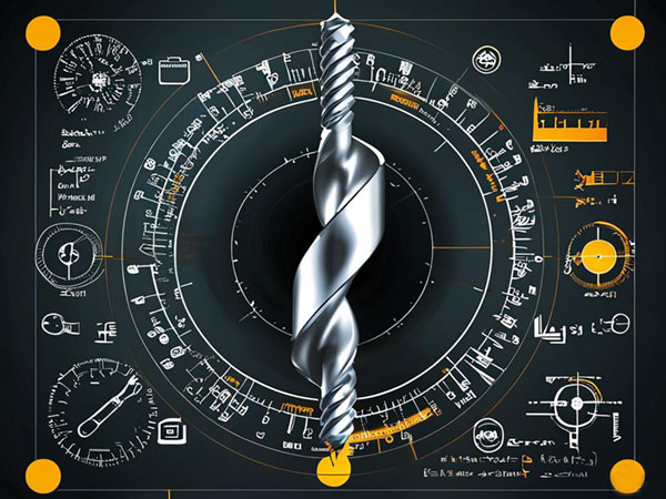
The helix angle of a milling cutter (Helix Angle) refers to the angle between the tangent of the helical cutting edge and the tool’s axis (commonly denoted as β). This angle is formed through precision grinding during tool manufacturing and essentially represents the geometric projection of the cutting edge in three-dimensional space (see Figure 1).
- Mathematical Expression: (tan β=πD ÷ L )
(Where D is the tool diameter and L is the lead of the helix.)
- Industrial Standard Range: Common helix angles range from 30° to 60°, with special tools reaching up to 70°.
- Measurement Reference: Defined as the angle between the unrolled helix line and the tool’s central rotation axis.
Common Misconception Correction
Many users mistakenly equate the helix angle with the rake angle. In reality, they are fundamentally different. For instance, a milling cutter with a 55° helix angle may have a rake angle of only 12°, and both contribute to the cutting performance.
2. Core Functional Mechanisms of the Helix Angle
2.1. The "Highway" of Chip Control
- Chip Evacuation Efficiency:
Every 10° increase in the helix angle improves chip evacuation speed by 15%–20%. When machining sticky materials like stainless steel, a 55° helix angle reduces the rate of built-up edge formation by 83% compared to a 40° angle.
- Case Study:
For a Vietnamese client machining SUS304 stainless steel flanges, switching to a 53° helix angle cutter reduced chip removal stoppages by two cycles per machining period.
2.2. The "Invisible Regulator" of Cutting Forces
- Balancing Axial and Radial Forces:
| Helix Angle | Axial Force Proportion | Radial Force Proportion |
|---|
| 30° | 65% | 35% |
| 45° | 50% | 50% |
| 60° | 35% | 65% |
|
- Measured Data: When machining 40CrMo steel, a 45° helix angle cutter reduced vibration amplitude by 42% compared to a 30° cutter.
2.3. The "Optical Key" to Surface Quality
- Controlling Surface Waviness:
When the spindle speed and helix angle satisfy the formula: ( n=60Vc ÷ (πD⋅tanβ))
(where nn is spindle speed and VcVc is cutting speed), the best surface finish can be achieved.
- Example:
A German client machining precision guide rails combined a 48° helix angle with 6000 rpm, improving surface roughness from Ra1.6μm to Ra0.4μm.
2.4. The "Time Manager" of Tool Life
- Optimizing Heat Distribution:
High-helix tools (55°–60°) increase the heat dissipation length by 30%, preventing localized overheating.
- Laboratory Data: When machining titanium alloys, a 55° helix angle reduced tool flank temperature by 120°C compared to a 40° cutter, extending tool life by 2.8 times.
3. Dynamic Modeling of Helix Angle Effects
3.1. Material-Angle Response Curve (For 45# Steel)
| Helix Angle | Cutting Force (Fz/N) | Surface Roughness (Ra/μm) | Tool Wear (VB/mm) |
|---|
| 30° | 520 | 1.8 | 0.25 |
| 45° | 420 | 1.2 | 0.18 |
| 60° | 380 | 0.8 | 0.35 |
(Test Conditions: Vc = 150 m/min, fz = 0.1 mm/z, ap = 5 mm)
3.2. Angle-Frequency Coupling Effect
- FFT analysis reveals:
- 30° cutters show main vibration frequencies at 800–1200 Hz.
- 45° cutters shift to 1500–1800 Hz.
- 60° cutters exhibit high-frequency vibrations above 2000 Hz.
- Solution: If the machine tool’s natural frequency is 1600 Hz, avoid using 45°–50° helix angle cutters.
4. Performance Variations in Special Applications
4.1. "Angle Attenuation" in Deep Cavity Machining
- When cutting depth exceeds 3 times the tool diameter:
- The effective helix angle decreases by 5°–8°.
- Compensation via gradient helix angle technology is recommended (e.g., increasing shank-end angle by 3°–5°).
4.2. "Angle Splitting" in Composite Material Machining
- For carbon fiber reinforced plastics (CFRP):
- Axial helix angle: 35° (to prevent delamination).
- Radial helix angle: 55° (to ensure fiber shearing).
- Case Study:
- A dual-helix cutter customized for a French aerospace company reduced CFRP machining defect rates from 12% to 0.7%.
5. Quick-Reference Guide to Helix Angle Selection
5.1. Core Rule: "Three Factors, Three Adjustments"
- Material Hardness
- Soft materials (Aluminum/Copper) → 55°–60°
- Medium-hard materials (Steel/Stainless Steel) → 40°–50°
- Hard materials (Hardened Steel/Titanium) → 30°–38°
- Machining Type
- Roughing → Reduce base angle by 3°–5° (for rigidity).
- Finishing → Increase base angle by 2°–3° (for smoothness).
- Machine Tool Performance
- Older machines → Reduce helix angle by 5° (to prevent vibration).
- High-speed machining centers → Increase helix angle by 3° (for efficiency).
5.2. Quick Formula (5-Second Calculation)
- Base Helix Angle=Material Hardness (HRC)×0.6+15
Base Helix Angle=Material Hardness (HRC)×0.6+15
- Example:
- 45# Steel (HRC 25) → 25×0.6+15=30°25×0.6+15=30° → Actual 45° (compensation for steel).
- 6061 Aluminum (HRC 15) → 15×0.6+15=24°15×0.6+15=24° → Actual 58° (soft material compensation).
6. Conclusion
The essence of helix angle selection lies not in finding the perfect angle but in achieving the optimal balance. Next time you're confronted with complex angle parameters, remember: each number encapsulates the precision interplay of material mechanics, manufacturing processes, and human ingenuity.


 We like to do design according to all the customers' requirements, or offer them our new designs. With strong OEM/ODM capabilities, we can fill your sourcing demands.